

Preventative Maintenance with
Infrared Thermography
Infrared is the best diagnostic tool for finding hot connections in the early stages of deterioration. Regular infrared inspections are the key to running an efficient and safe operation. The scans should also be combined with timely, effective repairs.
If you are installing, upgrading, or maintaining your commercial power system, please give us a call and set up an electrical infrared scan of your site.
If you are installing, upgrading, or maintaining your commercial power system, please give us a call and set up an electrical infrared scan of your site.
Benefits of infrared inspections
- Reduce unscheduled down time
- Increase equipment life and performance
- No service interruption during inspection
- Lower risks
- Lower repair costs
- Prevent catastrophic failures
- Lower insurance premiums due to reduced losses
- Saves money
Detectable conditions
- Loose/deteriorated connections
- Overloaded circuits
- Unbalanced loads
- Defective breakers
- Damaged switchgear
- Faulty fuses
- Defective equipment

Preventative Maintenance
Arc Flash
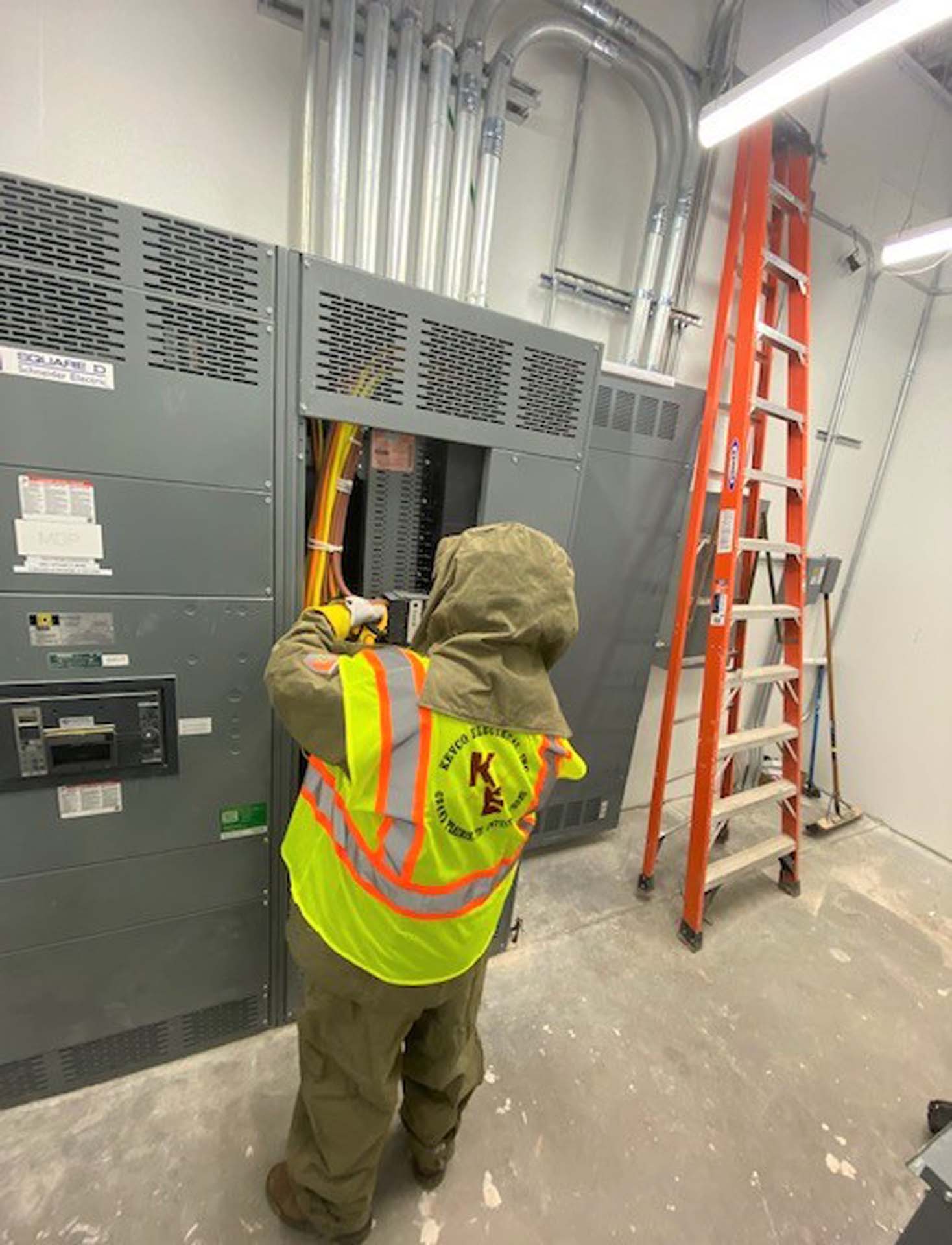
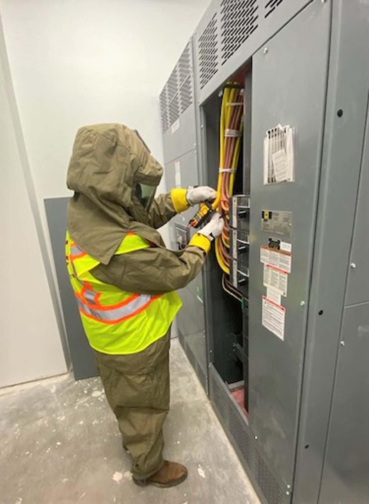
Arc flash risk assessments are a critical part of the electrical pre-work being performed by Kevco Electrical on every job every day. The assessment will determine the likelihood of creating an arc, the arc flash boundary, the available incident energy at the working distance, and the PPE required for all portions of the worker’s body within that boundary. Each electrical apparatus and equipment shall have an Arc Flash label installed on the front cover, identifying Arc Flash requirements as defined in various standards and regulations set forth by NFPA 70e, OSHA, and other groups committed to electrical safety and safeguarding employees.
We ask our customers to help us comply with these requirements by installing these Arc Flash labels on all their electrical equipment. Kevco Electrical has the engineering and expertise to furnish and install these Arc Flash labels.
We ask our customers to help us comply with these requirements by installing these Arc Flash labels on all their electrical equipment. Kevco Electrical has the engineering and expertise to furnish and install these Arc Flash labels.
According to NFPA 70E, there are 7 main steps that need to be taken on a study like this:
1. Acquire As-Built documentation
As-builts, One Line Diagram
2. Field verify
Equipment covers need to come off so we can visually inspect and acquire PD (protective device) manufacturer/types/sizes/settings, cable type/lengths, transformer impedance values, and KVA sizes.
3. Load information
4. Run a short circuit study
We review the 3 phase and single line to ground fault currents against the protective device “duty rating” to ensure the device can clear the fault. If the available fault current is less than the duty rating of the device, the device will do what it is intended and manufactured to do (clear it).
5. Perform a coordination study
In a properly coordinated system, the nearest protective device upstream of the fault will clear the fault without affecting protective devices further upstream. This will limit the impact of a fault on the overall electrical distribution only to where the fault is located.
6. Evaluate ARC flash
Provide recommendations to lower the incident energy levels including maximizing coordination.
7. Evaluate the system
Generating and applying the Arc, Flash labels, Training of the electrical staff, PPE requirements
Source: https://www.hallam-ics.com/blog/the-7-steps-to-complete-an-arc-flash-analysis

Short Circuit Analysis and
Breaker Coordination
In a properly coordinated system, the nearest protective device upstream of the fault will clear the fault without affecting protective devices further upstream. This will limit the impact of a fault on the overall electrical distribution only to where the fault is located.
To be assured that all over-current protection devices are coordinated, it is necessary to look at the time vs. current characteristics of each device and compare them to the characteristics of any upstream devices.
To be assured that all over-current protection devices are coordinated, it is necessary to look at the time vs. current characteristics of each device and compare them to the characteristics of any upstream devices.
Poor coordination
Ideally, where a fault occurs, the localized protective device should clear the fault. Otherwise, the fault travels back through the system and may trip the building’s main service device, thus losing power to the entire facility.
Improved coordination
We can clean up the coordination issues by adjusting the settings of those protective devices that cross over on the time-current curve. The fault clears at the fault location. Adjustments that we typically make on a protective device (i.e. circuit breaker with these options) include long time delay, short time pickup, short time delay, and instantaneous.

Updated panel schedules
Circuit Mapping/Coordination
Where does your circuit breaker go in your office? Believe it or not, you probably can’t tell even after you open the breaker panel door. Most panel schedules are either non-existent or out of date and impossible to read.
Electrical breaker panel schedules are one of your building’s most important pieces of equipment. Without them, you have absolutely no idea where each circuit breaker goes. Good luck next time you reset one and find out yours is poorly marked. When you hear the scream from the next office, you know you hit the wrong one!
It is important to take care of your electrical breakers annually or bi-annually and update your panel schedules to ensure a smooth-running building. Schedule routine maintenance like IR (infrared) scans to ensure there is no overheating, check to ensure the panels are clean, dry, and have no holes that critters can crawl into, bi-annual regular breaker torquing to keep them running properly. Take care of your breaker panels; they will keep you powered up!
Ensure your electrical infrastructure is organized and works as efficiently as possible. A contract is needed to make an on-site visit to provide a quote.
Where does your circuit breaker go in your building?
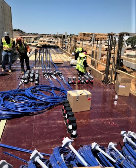
Our new Tasco CMT42DS 42 Remote Circuit Tracer Mapper is a unique and game changing tester and wire tracer, which enables us to trace multiple circuits and their branches at the same time. This circuit tracer mapper system greatly reduces man-hours spent when locating branch connections of electrical circuits.